Resultant Shear Force Formula
Determine the resultant shear forces in the rivets A and B. F_x2 Mark the midpoint of the resultant force F and draw the circle.

Determine The Resultant Force And Specify Where It Acts On The Beam Youtube
P total concentrated load lbs.

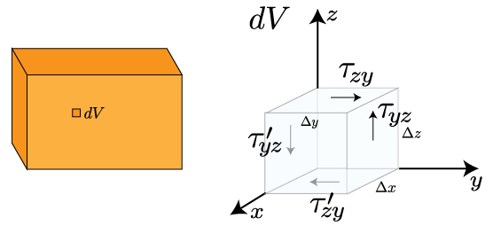
Resultant shear force formula. Is it pinned fixed or multiple. OverrightarrowR overrightarrowF_1 overrightarrowF_2 overrightarrowF_3 The parallelogram law triangle rule and polygon rule are geometric methods to find the force resultant. Displaystyle beginbmatrixV_2V_3endbmatrixint _-b2b2int _-t2t2beginbmatrixsigma _12sigma _13endbmatrixdx_3dx_2.
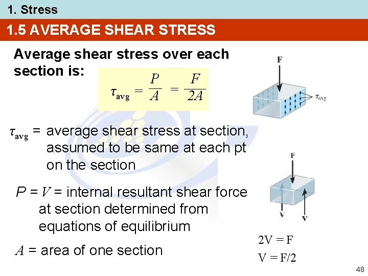
Shear force is usually denoted as V or Ved and the units are in kilonewtons kN Newtons N or pounds Ibf in engineering calculations. The vertical shear force on each rivet is 56 083 kN. The shear force intensity varies from zero at the top and bottom y h2 to a maximum value at the neutral axis at y 0 From Eq.
The total length of the downward pointing line is equal to the sum of all the downward forces and is known as the Resultant. Shear force in beams formula. Posted on June 14 2021 by.
The bracket shown in Fig. 912 we can write the following static equations. A v.
Convert Result to Outputs Unit. The resistance of the. Evaluate Formula STEP 3.
947 s N zs cos ds Q x s N zs sin ds Q y. Adding a vertical component of Fm1 force to the vertical shear force FV1 and similarly adding a horizontal component of Fm1 force to the horizontal shear force Fh1 will give us the sum of two different forces in two directions. A C.
The stress resultant N Q balances the transverse shear forces Q x and Q y. The two circles with their forces are combined into one circle. Resultant Vertical Shear Force on Section N calculator uses vertical_shear_force_at_n Total normal force cos Angle of the base pi 180 Shear force sin Angle of the base pi 180- Weight of slice Vertical shear force at other section to calculate the Vertical shear force The Resultant Vertical Shear Force on Section N.
The total length of the upward pointing line is equal to the sum of all the upward forces and is known as the Equilibrant - because it is the force required to balance the two loads and maintain balance or equilibrium. Introduction Notations Relative to Shear and Moment Diagrams E modulus of elasticity psi I moment of inertia in4 L span length of the bending member ft. R span length of the bending member in.
The shear force formula depends on the support conditions of a beam ie. Similarly the shear force resultants are V 2 V 3 b 2 b 2 t 2 t 2 12 13 d x 3 d x 2. To find the applied shear and tensile forces on a particular bolt simply multiply the stresses by the area of the bolt being considered.
116S Pe r2r. SHEAR FORCE BENDING MOMENT DIAGRAM shear force the force that tends to separate the member balances the reaction RA M bending moment the reaction moment at a particular point section balances the moment RAx SHEAR FORCE BENDING MOMENT DIAGRAM. M maximum bending moment in-lbs.
Resultant Tool Force when Shear force on shear plane is given Solution STEP 1. Draw the normal force N which is normal to the friction force P. Extend the tools rake surface by extending a line along with it and mark it as friction force P.
Tan F R F c F f 1c Where. 5 the maximum shear stress that occurs at the Neutral Axis is. For the forces F_x and F_z draw their resultant force F.
1115 carries an offset load of 5 kN. The result indicates that the shear stress distribution over the cross section is parabolic as plotted in Fig. R reaction load at bearing point lbs.
V shear force lbs. The last thing is to combine these two forces using Pythagorass theorem and we will get the final resultant force acting on the bolt. Sh- shear force F shN- Force normal to the shear force Where F sh F shN R D From tool side RR equilibrium R F FN Where F Friction force at chip tool interface FN Force normal to rake face The circles drawn taking R or R as diameter which contains all the force components concerned as intercepts.
The resultant force on a rivet is then the vector sum of the forces due to P and Pe. In Plane Eccentrically Loaded Connections. For example when a I-beam is loaded the resultant shear acting on the beam needs to be checked against the resistance provided from its cross section.
Tan 1b F R C. The resultant force can be determined also for three-dimensional force systems by using the polygon rule. Convert Input s to Base Unit STEP 2.
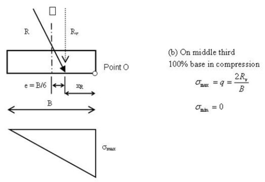
Acting over the cross section of a beam and the resultant shear force at the section is based on a study of the longitudinal shear stress and the results of VdMdx. K Pe r 2. A represents the concerned area for soil shear resistance plane area.
If all the bolts have the same cross sectional area then the force per bolt equals the connection force divided by the number of bolts. The value of resultant force F is calculated by a formulaF. We can draw the force resultant but we dont know precisely its magnitude and direction.
A F v. Determining the shear on bolts where the shearing force is in plane with the. Force shear resistance which is the sum of soil cohesional and soil frictional forces Eq.

Bending Shear And Moment Diagram Graphical Method To
Section Iii 4

Bending Moment And Shear Force Computation Bending Moment Shear Force In This Moment
Resultant Shear Force An Overview Sciencedirect Topics
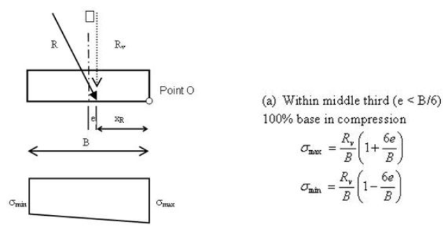
Chapter 4 Eccentricity Synthesis Of Geosynthetic Reinforced Soil Grs Design Topics February 2015 Fhwa Hrt 14 094

Determine The Resultant Force And Specify Where It Acts On The Beam Youtube
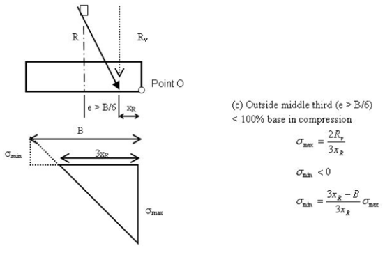
Chapter 4 Eccentricity Synthesis Of Geosynthetic Reinforced Soil Grs Design Topics February 2015 Fhwa Hrt 14 094

Determine The Magnitude And Direction Of The Resultant Force Youtube

Determine The Resultant Force And Specify Where It Acts On The Beam Youtube

Torsional Stress Calculator And Equations Engineers Edge Equations Stress Calculator

Resultant Force An Overview Sciencedirect Topics

Determine B Of The Triangular Load And Its Position A On The Beam Youtube

Coordinate Direction Angles Statics Tutorial Engineering Courses Directions

Determine The Resultant Force And Specify Where It Acts On The Beam Youtube
Mechanics Of Materials Stress Mechanics Of Slender Structures Boston University
1 Stress Chapter Outline 1 2 3 4
Chapter 4 Eccentricity Synthesis Of Geosynthetic Reinforced Soil Grs Design Topics February 2015 Fhwa Hrt 14 094

25a Bending Equilibirum And Resultant Stress Relations Youtube
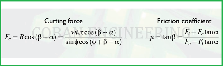
Cutting Forces And Chip Formations Formulas Forces In Metal Cutting Forces In Metal Cutting Formulas Cutting Shear Stress Formulas Friction Coefficient Formulas
Posting Komentar untuk "Resultant Shear Force Formula"