Resultant Bending Moment Formula
Since there are no other loads applied between the first and second cut the bending moment equation will remain the same. Equations for Resultant Forces Shear Forces and Bending Moments can.

Resultant Moment And Shear Force At The Maximum Impact Force Download Scientific Diagram
The moment resultant per unit reference surface circumferential length Mx is given by.

Resultant bending moment formula. The internal reaction loads in a cross-section of the structural elements can be resolved into a resultant force and a resultant couple for equilibrium the moment. For dished ends the resultant shear force and bending moment are calculated as. A Calculate the shear force and bending moment for the beam subjected to a concentrated load as shown in the figure.
Using the improved model an ultimate bending moment formula is presented. Then draw the shear force diagram SFD and bending moment diagram BMD. Determine the resultant couple moment by a summing moments about point O and b summing the moments about point A.
M F x d y F y d x. Solution Note that the triangular load has been replaced by is resultant which is the force 05 12 360 2160 lb area under the loading diagram acting at the centroid of the loading diagram. Neglect the weight of the beam.
Simply select the picture which most resembles the beam configuration and loading condition you are interested in for a detailed summary of all the structural properties. The resultant bending moment M bend acts in the middle of the femoral neck and perpendicular to the neck axis and is calculated with the following formula. When completing part a I found the following answer.
Shear and moment diagram for a simply supported beam with a concentrated load at mid-span. BEAM DIAGRAMS AND FORMULAS Table 3-23 continued Shears Moments and Deflections 13. Bending moments produced by lift generally have only a small effect on the resultant bending moment.
The forces F x F y F z and moments M x M y M z are measured in the implant coordinate system x y z centered in the middle of the implant headThe force component F x acts laterally F. In contrast because of the rectangular differential area of the adjacent cross-section d A d x d z the resultants Ns and Ms are given by. To give this moment the resultant force must be a distance of 475150 32 m from A.
This is mainly the sound which the automatic gear boxs fluid. And 2 draw the shear force and bending moment diagrams. -Mx 10-x Mx 10x.
The internal stresses in a cross-section of a structural element can be resolved into a resultant force and a resultant coupleFor equilibrium the moment created by external forces and external moments must be. The bending moment is defined as the external load is applied in a beam element to bend. M bending moment Nm lb in I moment of Inertia m4 mm4 in4 The maximum moment in a cantilever beam is at the fixed point and the maximum stress can be calculated by combining 1b and 1d to max ymax F L I 1e.
The bending moment is generated. In solid mechanics a bending moment is the reaction induced in a structural element when an external force or moment is applied to the element causing the element to bend. Stress resultants are simplified representations of the stress state in structural elements such as beams plates or shells.
The resultant force 100 150 200 150 N in a downward direction. A bending moment is a measure of the average internal stress induced in a structural element when an external force or moment is applied to the element causing the element to bend. 97M x dMx Rd H 2 H 2 z x1 z Rdz.
P kN L2 L2 A B EXAMPLE 4. Bending Moment Formula and Equations offer a quick and easy analysis to determine the maximum bending moment in a beam. Below is a concise table that shows the bending moment equations for different beam setups.
This cut is made just before the second force along the beam. Introduction Notations Relative to Shear and Moment Diagrams E modulus of elasticity psi I moment of inertia in4 L span length of the bending member ft. Dont want to hand calculate these sign up for a free SkyCiv Account and get instant access to a free version of our beam software.
Shear and moment diagrams and formulas are excerpted from the Western Woods Use Book 4th edition and are provided herein as a courtesy of Western Wood Products Association. F SQRT F L 2 F C 2 M SQRT M L 2 M C 2 The loads stated. M O F x d y F y d x 9686 k N M.
Bending Moment- Types Formula Limitations Types of Bending Stress What is the banding moment of the beam. I used scalar analysis for solving this question wherein. Beam equations for Resultant Forces Shear Forces Bending Moments and Deflection can be found for each beam case shown.
98N s H 2 H 2 sdz M s H 2 H. Beam Design Formulas. The geometry of typical structural elements allows the internal stress state to be simplified because of the existence of a thickness direction in which the size of the element is much smaller than in other directions.
The shear and bending moment of beam cross - section were calculated by the internal function of Excel. The moments of the forces about A 100 15 150 25 200 35 475 Nm in a clockwise direction. B If P 20 kN and L 6 m draw the SFD and BMD for the beam.
The equation for this part of our bending moment diagram is. BEAM FIXED AT ONE END SUPPORTED AT OTHER-CONCENTRATED LOAD AT CENTER. Shear force and bending moment equations.
Simply select the picture which most resembles the frame configuration and loading condition you are interested in for a detailed summary of all the structural properties.

Resultant Of Couples Example Youtube

Bending Shear And Bending Moment Diagrams Covered In

Determine The Resultant Couple Moment Acting On The Beam Youtube

Schematic Description Of The Resultant Bending Moment Caused By Download Scientific Diagram

Bending Moment And Shear Force Computation Bending Moment Shear Force In This Moment

Mechanical Engineers Rocks Engineering Science Mechanical Engineering Physics And Mathematics

Determine The Resultant Force And Specify Where It Acts On The Beam Youtube

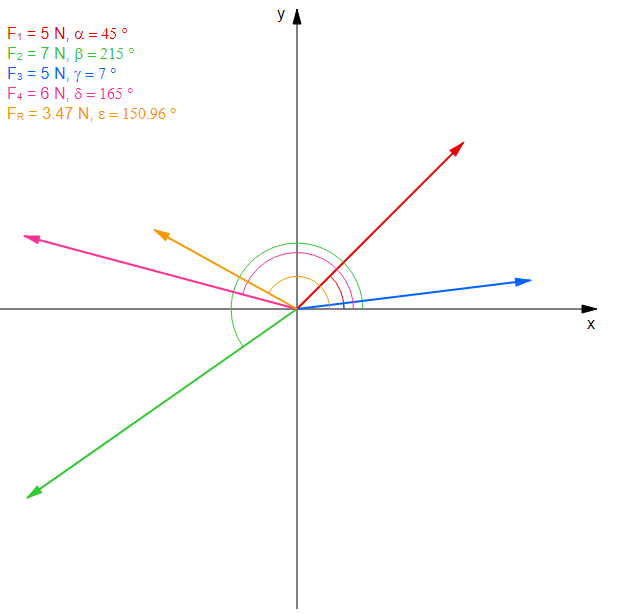
Online Calculator Resultant Force 4 Concurrent Forces Pickedshares

Calculation Of The Resultant Force Mechanics Exercise And Solution

Image Result For Resultant Of Two Inclined Forces

Projectile Motion Of A Tennis Ball Teaching Resources Projectile Motion Engineering Science Tennis Ball

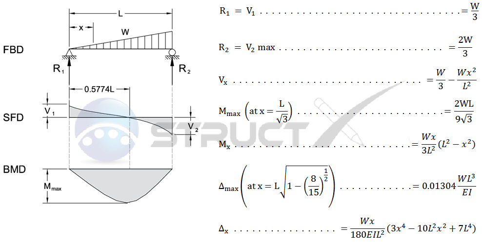
Simple Beam Uniformly Increasing Load To One End

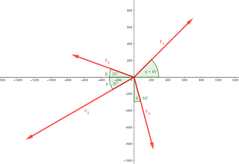
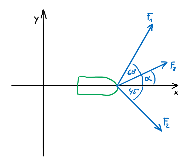
Determine Missing Force And Angle With A Given Resultant Force

Stick S Lightweight Structural System Asknature Human Bones Bending Moment Biomimicry Examples

25a Bending Equilibirum And Resultant Stress Relations Youtube

Resultant Moment And Shear Force At The Maximum Impact Force Download Scientific Diagram

Coordinate Direction Angles Statics Tutorial Engineering Courses Directions

Posting Komentar untuk "Resultant Bending Moment Formula"